REPLACEMENT OF DAMAGED FUEL CAM
As requested, our service team visited the vessel to replace NO:4 fuel cam while berthed at Port.
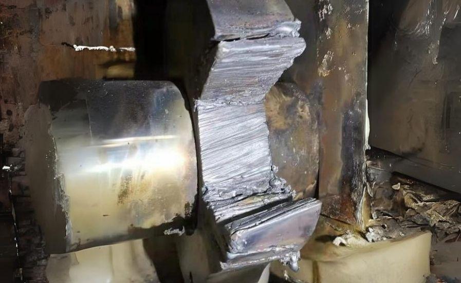
As per the available info, previously another service team already cut both side of cam and applied 25 Ton hydraulic jack but not able to remove the cam from camshaft due to friction welding between cam and camshaft.
On first inspection, we have confirmed the friction welding since melted metals leaked out between cam and camshaft.
As owner do not allow us the apply hydraulic jack which could be more easy, damaged cam removed from the shaft as
below sequence within very limited time.
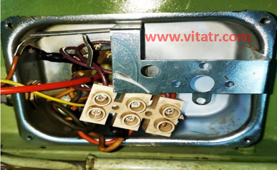
- Arranging protection of camshaft bearings, roller guide and camshaft area against to foreign particle.
- Gas cutting of remaining part of cam above 100 mm of camshaft by controlling the shaft temperature by laser gun and allow max temperature up to 60 °C
- Only compressed air used to cooling down the camshaft when necessary, water cooling did not applied.
- Cutting remaining part of cam up to 15 mm above the camshaft by cutting stone without using any flame.
- Manuel grinding of remaining cam parts up to 3-4 mm above the camshaft.
- Semi auto grinding of remaining part by special tool fabricated for this purpose only.
- Polishing the surface with 3M brand 30 micron abrasive by using air powered tool.
- Visual check and dye penetrant test of cam surface for any crack and damage.
- Checking the surface by steel rule and light to confirm surface is same level with camshaft.
- Applying blue colour check on the camshaft and new split cam for final verification.
- Assembling the new split cam and roller.
- Adjusting the fuel cam lead to 17.5 mm as indicated on shop test report of engine.
- Tightining the bolts up to specified torque by applying loctite thread locker.
- Re-check the timing.
- Marking zero mark on the both cam and camshaft in order to check cam position in the future.
Cam not equally/evenly welded on the camshaft, which means surface is not smooth as new camshaft surface, but it can
be ignored because new cam seating area is extended by maker for this purpose.


Several incidents reported that some or all the exhaust or fuel cams lost their correct position due to roller damages. In that case, cams in questions to be adjusted back to correct position.
- One of the common reasons of the roller damages is malfunction of the reversing system. In case the reversing is not complete or doesn’t take place, forces acting on the roller guide and reversing arm is so high that it can cause such damage to the components. Adjustment of the reversing arms to be checked during overhaul of the roller. Please see service letter SL1988-243 in line with maintenance manual related section in Plate no 909.
- Another possible reason of the roller damages is water leakages to roller sections. In case no effective sealing between roller housing and engine frame, and excessive water leak from cooling jackets with blocked drains, it is possible to water enter to roller housing and break the oil film which result stuck of the roller. Therefor it is very important to keep engine free from any leakages and make sure drain holes not blocked by foreign materials.
- Roller overhaul and inspection should not be skipped and to be completed together with fuel pump overhauls. Crack tests will inform you in advance if any crack developed on the rollers which will cause damage in due course. Loose guide blocks also will cause misalignment and damage of the roller. Please see service letter SL1997-345 for more info.
- Our experience shows that in some cases, it is overlooked to order seal & O-rings set for roller housings and umbrella seals, resulting cancelling roller overhaul and inspection, which should be done together with fuel pump overhaul during drydocks. Therefore, we recommend keep full set seal and O-ring for the roller and umbrella seal system on board.
- We also recommend keeping below spares on board to prevent operational time losses.
- 1 pc two halves exhaust cam.
- 1 pc two halves fuel pump cam
- 1 set fuel pump roller
- 1 set exhaust cam roller
- 1 pc fuel roller housing
- 1 pc exhaust roller housing
- 1 pc spring for fuel and exhaust roller
Recommendation: